Introduction to 7Segment Display :
The Seven Segment displays are commonly used to display alpha-numerics, which have 7 straight LEDs arranged in 8 format and a dot shaped LED at right bottom corner, packed in a rectangular shape

There are two types of 7 segment displays, while considering internal electrical circuit.
1) Common Anode Displays
2) Common Cathode Displays
If all the anodes of the 8 LEDs in the package are connected to common wire, which is available as one or two pins externally and all the cathode pins are available individually, externally, then it is called Common Anode (CA) displays.
Similarly, if all the cathodes of the 8 LEDs in the package are connected to common wire, which is available as one or two pins externally and all the anode pins are available individually, externally, then it is called Common Cathode (CC) displays.
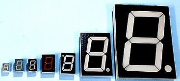
The 7 segments are available in various sizes from 1/4" to 4" or more. The pin diagrams (pinouts) depends on manufacturers and size. Now-a-days, 7 segments displays can emit various colours (using various colour LEDs), like, red, green, blue, white and multi-colour also.

The seven segment LEDs are identified as a,b,c,d,e,f,g and the round LED as dp (decimal point). Some vardious sizes of 7 segment displays and a model 7 segment display with segment and pin connections are shown here, for easy understanding.


Connecting 7Segment Display to Arduino :
To connect a 7 segment display to Arduino, the 8 pins of built-in LEDs (available in rectangular package) have to be connected to 8 pins of Arduino, through series resistances. The common pin(s) have to be connected to either 5V (for Common Anode) or Ground (for Common Cathode) pins.
A test circuit diagram of conecting 7 segment display (CA & CC) to Arduino Nano is shown below.


Now, open File->New in Arduino IDE, then initially, declare the pin connections of 7 segment display to Arduino pin connections, in proper order, as shown below.
// Pin connection sequence a , b , c , d , e , f , g , dp
int segPins[] = { 4, 5, A4, A3, A2, 3 ,2, A5 };
Then, set the declared pins as out put using pinMode function in setup function, as shown below.
void setup()
{
// set all 8 pins as output
for (int i = 0; i < 8; i++)
{
pinMode(segPins[i], OUTPUT);
}
}
Then, let the each segment glow, one-after-another in sequence, as a self test. So, in the loop function, start with switching OFF all the segments and dp in a for loop using digitalWrite as LOW. Then, switching ON each segment, one-by-one, in consecutively using digitalWrite as HIGH. A delay function is used to visualize the sequence of glowing each LED easily.
void loop() // for CC display
{
for (int i = 0; i < 8; i++)
{
digitalWrite(segPins[i], LOW ); // 0
}
for (int i = 0; i < 8; i++)
{
digitalWrite(segPins[i], HIGH ); // 1
delay(1000);
}
}
The above sketch is written for Common Cathode display. For, Common Anode Display, invert the key word LOW with HIGH and vice-versa. In case of Common Anode, the common pin should be connected to 5V pin and incase of Common Cathode, the common pin should be connected to GND pin of Arduino.
In place of HIGH, 1 may be used and similarly, in place of LOW, 0 (zero) may be used. The loop function is modified for Common Anode and using 0 and 1 in place of LOW and HIGH keywords below.
void loop() // for CA display
{
for (int i = 0; i < 8; i++)
{
digitalWrite(segPins[i], 1 ); // HIGH
}
for (int i = 0; i < 8; i++)
{
digitalWrite(segPins[i], 0 ); //LOW
delay(1000);
}
}
So, you have to invert the LOW to HIGH and vice-versa for CA and CC displays and connect to 5V or GND pins for CA or CC displays. The successive coding (sketch) is written for CC only and follow the same rule for CA displays, which are marked as remarks /* */ in brown colour.
Showing Numbers on 7Segment Display :
To show Numbers on a 7 segment display using Arduino (or a micro-controller), the segments' ON/OFF control is to be declared initially, in an array, for easy editing and accessing the code to be displayed. Here, integer array is declared, using code 1 for ON and 0 (zero) for OFF state of each segment and dp sequentially, to display number 0 to 9 and dp LED (as 10). Remember to declare the array before setup function, as shown below.
// Pin connection sequence a , b , c , d , e , f , g , dp
int segPins[] = { 4, 5, A4, A3, A2, 3 ,2, A5 };
int number[11][8] =
{
{ 1, 1, 1, 1, 1, 1, 0, 0 }, // 0
{ 0, 1, 1, 0, 0, 0, 0, 0 }, // 1
{ 1, 1, 0, 1, 1, 0, 1, 0 }, // 2
{ 1, 1, 1, 1, 0, 0, 1, 0 }, // 3
{ 0, 1, 1, 0, 0, 1, 1, 0 }, // 4
{ 1, 0, 1, 1, 0, 1, 1, 0 }, // 5
{ 1, 0, 1, 1, 1, 1, 1, 0 }, // 6
{ 1, 1, 1, 0, 0, 0, 0, 0 }, // 7
{ 1, 1, 1, 1, 1, 1, 1, 0 }, // 8
{ 1, 1, 1, 1, 0, 1, 1, 0 }, // 9
{ 0, 0, 0, 0, 0, 0, 0, 1 } // dot or dp
};
There is no change in setup function. Now, you have to control the output code at 8 pins of Arduino board. For showing the number as per the code declared in the array, a user defined function, show, is to be added in between setup and loop functions.
void show ( int n ) // n is the row number of the array
{
for (int i = 0; i < 8; i++) // elements (or columns) in each row of array
{
// write each element to each pin of Arduino as per the value 1 or 0
digitalWrite(segPins[i], number[n][i]); // for CC
/* digitalWrite(segPins[i], 1-number[n][i]); // invert for CA */
}
}
Now, you have to write code to display the numbers (and dp) sequentially in loop function as shown below.
void loop() {
for (int i = 0; i < 11; i++) // select each row of the array
{
show ( i ); // show the code written for the row in the array
delay(1000);
}
}
The output is shown below:

Showing Alphabet on 7Segment Display :
7 segment displays are highly used to display numbers, but, it may be used to show specific Alphabet also, which are easy to read / understand. For showing Alphabet, similar to numbers, a new array declaration is required, using code 1 for ON and 0 (zero) for OFF state of each segment. The array is declared before setup function, as shown below.
// Pin connection sequence a , b , c , d , e , f , g , dp
int segPins[] = { 4, 5, A4, A3, A2, 3 ,2, A5 };
int alpha[16][8] = {
{ 1, 1, 1, 0, 1, 1, 1, 0 }, // A
{ 1, 1, 1, 1, 1, 0, 1, 0 }, // a
{ 0, 0, 1, 1, 1, 1, 1, 0 }, // b
{ 1, 0, 0, 1, 1, 1, 0, 0 }, // C
{ 0, 0, 0, 1, 1, 0, 1, 0 }, // c
{ 0, 1, 1, 1, 1, 0, 1, 0 }, // d
{ 1, 0, 0, 1, 1, 1, 1, 0 }, // E
{ 1, 0, 0, 0, 1, 1, 1, 0 }, // F
{ 1, 0, 1, 1, 1, 1, 0, 0 }, // G
{ 0, 1, 1, 0, 1, 1, 1, 0 }, // H
{ 0, 1, 1, 1, 1, 0, 0, 0 }, // J
{ 0, 0, 0, 1, 1, 1, 0, 0 }, // L
{ 1, 1, 0, 0, 1, 1, 1, 0 }, // P
{ 0, 0, 0, 1, 1, 1, 1, 0 }, // t
{ 0, 1, 1, 1, 1, 1, 0, 0 }, // U
{ 0, 1, 1, 1, 0, 1, 1, 0 } // Y
};
There is no change in setup and show functions. Now, you have to modify code to display the alphabet ( now the array size is 16 instead of 11 ) sequentially in loop function as shown below.
void loop() {
for (int i = 0; i < 16; i++) // select each row of the array; 16 rows
{
show ( i ); // show the code written for the row in the array
delay(1000);
}
}
The output is shown below:


Playing DICE with 7Segment Display :
As an entertainment, you may write a code to display random numbers 1 to 6, like a Dice (which is having 6 faces indicating 1 to 6 with dots on each face). The circuit diagram is shown below for digital dice display.

There is no much difference w.r.t. previous circuit, but, a push button switch is added in between pin 7 and pin GND of Arduino Nano board.
You may connect the push button switch to any button and declare the same number in the sketch (instead of 7).

The complete sketch for DICE is shown below with comments/remarks for easy understanding.
// Pin connection sequence a , b , c , d , e , f , g , dp
int segPins[] = { 4, 5, A4, A3, A2, 3 ,2, A5 };
#define readPin 7 // declare pin 7 as readPin for input
int num = 0; // declare num variable as counter (1 to 6)
// declare number array and set the code to be displayed
int number[11][8] =
{
{ 1, 1, 1, 1, 1, 1, 0, 0 }, // 0
{ 0, 1, 1, 0, 0, 0, 0, 0 }, // 1
{ 1, 1, 0, 1, 1, 0, 1, 0 }, // 2
{ 1, 1, 1, 1, 0, 0, 1, 0 }, // 3
{ 0, 1, 1, 0, 0, 1, 1, 0 }, // 4
{ 1, 0, 1, 1, 0, 1, 1, 0 }, // 5
{ 1, 0, 1, 1, 1, 1, 1, 0 }, // 6
{ 1, 1, 1, 0, 0, 0, 0, 0 }, // 7
{ 1, 1, 1, 1, 1, 1, 1, 0 }, // 8
{ 1, 1, 1, 1, 0, 1, 1, 0 }, // 9
{ 0, 0, 0, 0, 0, 0, 0, 1 } // dot
};
//==========================
void setup()
{
// select and set all the pins as output
for (int i = 0; i < 8; i++)
{
pinMode(segPins[i], OUTPUT);
}
pinMode(readPin, INPUT); // set the readPin i.e., 7 as input to read the digital value
digitalWrite(readPin, HIGH); // internal pull-up resistor activated
show ( 0 ); // intially show zero
}
//==========================
void show ( int n ) // function to show the required number / dp
{
for (int i = 0; i < 8; i++) // show the code for each pin (total 8 pins connected)
{
// output the code to specific pin ( 1 to 8 ) as per the number (CC)
digitalWrite(segPins[i], number[n][i]);
// use following statement in case of Common Anode Display
/* digitalWrite(segPins[i], 1-number[n][i]); // invert for CA */
}
}
//==========================
void loop() {
// check and run the code when button is PRESSED
if ( digitalRead ( readPin ) == LOW )
{
show ( 10 ); // show DOT only when button is PRESSED
num++; // increment number when button is PRESSED
if (num>6) // reset to 1 if exceeds 6
num = 1;
}
else // run this code when button is NOT PRESSED
show( num ); // show the current number when button is NOT PRESSED
}
//==========================